Base de conocimientos RF 10 min read

NetPoint basic
RF knowledge

Autor

David Alvarez

Publicado

Enero 01, 2023

Mobirise

How to Properly Align NetPoint Antennas

Things to learn

Main lobe
Beamwidth
Secondary lobe
Null signal

How Antennas Operate

Mobirise

Main lobe 

It is the main area where we are going to position our antennas. It is the point of best efficiency and capacity.

Mobirise

Null signal 

A space/s without radiated energy, between the main and secondary lobe.
"It is where you sometimes lose the signal when aligning."

Mobirise

Secondary lobes 

They are energy leaks from the main lobe and all antennas have them.

Aligning a NetPoint Antenna

Alineando una antena NetPoint

1.- How to choose a frequency to align? 

Instalacion con antena NP1 y B5C
Antenas NetPoint ¿Como puedo optimizar mi zona Fresnel en un radioenlace?

How can I optimize my Fresnel zone in a radio link?

Autor: Ing. David Alvarez

Check the height of the antennas: The both ends of the link can affect the fresnel zone. Netpoint antennas must be high enough to have a good line of sight and to minimize obstacles in the fresnel zone.

Obstacles: In the Fresnel zone they can obstruct or reflect the radio frequency signal, which can affect the quality of the link. The location of obstacles in the Fresnel zone should be checked and if possible, removed or minimized.

Verify the orientation of the antennas: The orientation of the antennas at both ends of the link can affect the fresnel zone. The antennas must be properly oriented to have a good line of sight and to minimize long-term problems. 

Continuous improvement 
Enero 02, 2023

What are the best parameters to say that I have a good internet radio link?

The parameters that are usually considered to evaluate the quality of an Internet radio link are:


Data transfer speedThe data transfer speed is the amount of data that can be transmitted in a given period of time. It is usually measured in bits per second (bps) or megabits per second (Mbps). A higher data transfer rate indicates better link quality.

LatencyLatency is the time that elapses between the sending of a data packet and its reception at the destination. Low latency indicates better link quality.


ReliabilityThe reliability of the link refers to its ability to transmit data without interruptions or packet loss. A more reliable link will have better quality.


SignalSignal is the strength of the radio frequency signal that is used to transmit data. A stronger signal indicates better link quality.

In general, a good quality internet radio link will have a high data rate, low latency, high reliability, and a strong signal. However, it must be borne in mind that these parameters may vary depending on the conditions. 

Mobirise

Why is it difficult to make a radio link at sea level?

There are several factors that can make it difficult to make a radio link at sea level:

Electromagnetic interference:
The sea can be a source of electromagnetic interference for radio links, since water is a conductor of electricity and can reflect radio frequency signals. This can make it difficult to receive and transmit signals.

Weather conditions:
Weather conditions at sea level such as rain, fog and snow can affect the quality of a radio link signal. These make it difficult to establish and maintain a good quality link, but can be mitigated with a radome.

Obstacles:
Obstacles in the line of sight between the antennas, such as waves and ships, can obstruct or reflect the radio frequency signal, which can affect the quality of the link, so we choose to find the highest height .

Installation and maintenance:
Installing and maintaining a radio link at sea level can be difficult due to weather conditions and the lack of access to the location of the antennas. This can increase the time and cost required to establish and maintain a link.

In general, making a radio link at sea level can be difficult due to adverse environmental and technical conditions and lack of access to antennas. However, there are technologies like NetPoint's and specific techniques that can be used to mitigate these issues and establish a good quality link

About antenna maintenance

How can I prevent water from entering my antennas?

1.- Protect the antenna with a cover or radome
Antenna covers protect the antennas from the weather and prevent water from entering the interior. Antenna covers of different materials and sizes can be used, depending on the type of antenna and weather conditions. 

Radomo y cubiertas para antenas NetPoint
Sellado de conectores de antenas

Seal Connectors

Antenna connectors are vulnerable points where water can enter the interior. Special sealants can be used to seal the connectors and prevent water from entering the interior of the antenna, the ideal is to do it from where the feeder starts.

Example: You cannot leave your facilities like this because at some point it will fail.

Scheduled Maintenance

Regularly check the antennas
It is important to regularly check the antenna to detect and repair any damage or wear off that could allow water to enter the interior. If the antenna is found to be damaged or not working properly, immediately repair or replace it to prevent more serious problems in the future. 

antena NetPoint mantenimiento

What is beam width?

The beamwidth of a parabolic dish like NetPoint is the angle at which radio frequency signals are emitted or received. The beam width of a  dish is measured in degrees and determines the amount of power that is transmitted or received in a specific direction.

Satellite dishes (NetPoint) have a narrower beamwidth than antennas of other shapes, which means they transmit or receive a greater amount of power in a specific direction.

This makes satellite dishes ideal for high-gain point-to-point links over long distances, as they can focus the signal in a specific direction and reduce interference from other signals. The beamwidth of a satellite dish can also affect the polarization of the transmitted or received signal. For example, a satellite dish with a vertical beamwidth will transmit a vertically polarized signal, while a satellite dish with a horizontal beamwidth will transmit a horizontally polarized signal. 

Ancho de haz

What is the use of the slant in the antennas ?

The slant is a term used to describe the tilt or tilt angle of a satellite dish. The slant refers to the vertical distance between the focus of the parabola and its center.

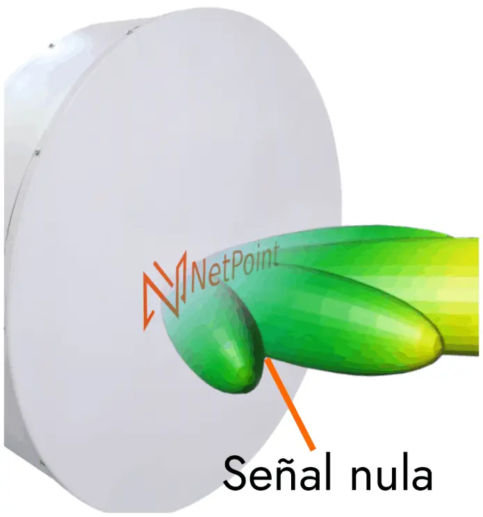
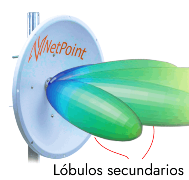
The slant is used to adjust the gain and direction of the satellite dish. A larger slant increases the gain of the antenna and makes it more sensitive to signals arriving from lower angles. On the other hand, a smaller slant decreases the gain of the antenna and makes it less sensitive to signals arriving from lower angles. 

Reimagining the works of modernist innovators

The slant is also used to focus the radio frequency signal in a certain direction. Proper slant can help maximize antenna gain and improve RF signal quality. 

What are the causes of interference on a backhaul link?

There are always many reasons for interference, but these are the most common:

Other nearby radio frequency links
Nearby radio frequency links can interfere with each other if they use the same or nearby frequencies. This can affect the quality of the backhaul link.

Obstacles
Obstacles in the line of sight between the antennas, such as trees, buildings, and mountains, can obstruct or reflect the RF signal, which can affect the quality of the backhaul link.

Electromagnetic Interference
Sources of electromagnetic interference, such as electric motors and electronic devices, can interfere with the radio frequency signal and affect the quality of the backhaul link.

Equipment failures
Failures in the radio frequency equipment used in the backhaul link, such as antennas, radios, and even poor cable and POE crimping can cause interference and affect the quality of the link. 

NetPoint en lluvia

¿Y el clima?

Weather can affect the quality of a radio link in several ways, depending on the specific weather conditions. Some of the effects of weather on a radio link are:

Electromagnetic interference: Water, snow and rain can be sources of electromagnetic interference to radio links, as they are conductors of electricity and can reflect radio frequency signals. This can hinder signal reception and transmission.

Obstacles: Wind, rain and snow can obstruct the line of sight between antennas, which can affect the quality of the RF signal. This can make it difficult to establish and maintain a good quality link.

Obstructed antennas: Wind, rain and snow can build up on antennas and obstruct signal transmission and reception. This can affect the quality of the link.

Can shielded antennas reduce electromagnetic interference?

yes, shielded antennas such as NPXGEN3 can help reduce electromagnetic interference from other RF sources. Electromagnetic interference is a form of electromagnetic noise that can adversely affect the quality of the RF signal.

Shielded antennas are designed to protect the RF signal from external electromagnetic interference. This is achieved by using a layer of conductive material, such as copper or aluminium, which surrounds the antenna and blocks external electromagnetic waves. Shielded antennas can be effective in reducing electromagnetic interference.

La ganancia de una antena

What influences antenna gain?

The gain of an antenna refers to its ability to focus the RF signal in a given direction. There are several factors that can influence the gain of an antenna:

Antenna geometry: The shape and size of the antenna can affect its gain. For example, high gain antennas tend to have a longer and narrower shape, while low gain antennas tend to have a shorter and wider shape.

Frequency of operation: The gain of an antenna can vary with the frequency of operation. For example, an antenna may have a higher gain at a frequency of 2.4 GHz than at a frequency of 5 GHz.

Antenna polarisation: The polarisation of the antenna, i.e. the orientation of the RF signal, can also affect its gain. For example, a vertically polarised antenna may have a different gain than a horizontally polarised one.

Wavelength: The wavelength of the RF signal can also affect the gain of the antenna. Antennas operating at longer wavelengths tend to have lower gain than antennas operating at shorter wavelengths.

Antenna efficiency: The efficiency of the antenna, i.e. the amount of RF signal energy that is converted into electromagnetic radiation, can also affect its gain. More efficient antennas have higher gain than less efficient ones.

How do NetPoint antennas work?

A dish dish antenna is a type of directional antenna used to send and receive radio frequency (RF) signals in a specific direction. The basic design of a dish antenna consists of a metal reflecting dish with a small transmit/receive antenna called a feed horn at the focal point of the dish. The dish has the geometrical shape of a parabola, which means that any electromagnetic wave incident on it is reflected back to the focal point.

When a signal is transmitted from the feed horn (dipole), the electromagnetic wave is reflected back into the parabola and concentrated at a focal point. This creates a highly directional signal beam, which is directed towards a single point in space. When a signal is received, the process is reversed: the signal is collected at the feed horn after being reflected by the parabola.

Why is an NPGEN2 or NPTR antenna optimised with an armour or shield?

El Escudo o armadura

Yes, it is possible to optimise the performance of an antenna by using an armour or shield. An armour or shield is used to protect the antenna from external electromagnetic interference (EMI) and radio frequency interference (RFI), which can improve its performance and increase its resilience.

An armour or shield is placed around the antenna and is made of a conductive material, such as aluminium or copper. The conductive material helps to reflect or absorb external electromagnetic waves, preventing them from propagating towards the antenna and causing signal interference.

In addition, a shield also helps to reduce the electromagnetic radiation emitted by the antenna, which can be beneficial in applications where low radiation emission is required, but beware that this must be well calculated to work because if you do it without a study you can lose the gain of your antennas.

Mobirise Website Builder

What is front-to-back?

Front-to-back ratio is a measure of the gain of an antenna that indicates the ratio of the gain of the received signal in the front direction of the antenna to the gain of the received signal in the rear direction of the antenna. It is measured in dB (decibels). An antenna with a high front-to-back ratio will have a higher gain in the front direction and a lower gain in the rear direction.

This means that the antenna is designed to pick up signals in a specific direction and reject signals in the opposite direction. For example, a transmit antenna must have a high front-to-back ratio to prevent transmitted signals from reflecting in the back direction and causing interference with other nearby networks. On the other hand, an antenna with a low front-to-back ratio will have similar gain in both directions, meaning that it is designed to pick up signals in both directions. These antennas are useful in point-to-multipoint communications applications where coverage in multiple directions is required.

What is TDMA?

TDMA (Time Division Multiplexing) is a multiplexing technique used in wireless radio systems, such as Mimosa radios, to allow multiple users to share limited bandwidth by dividing the transmission time into discrete segments and assigning a time segment to each user.

In radio systems using TDMA, each radio device communicates with a central controller at a specific time, and each device has access to the frequency band only at its assigned time, allowing multiple devices to share the same radio spectrum.

The TDMA technique allows for better bandwidth utilisation, as multiple devices can share the same frequency band. It also reduces communication delay and improves system efficiency by avoiding interference between devices.

In summary, TDMA (time division multiplexing) is a multiplexing technique used in wireless radio systems such as Mimosa radios to allow multiple users to share a limited bandwidth by dividing the transmission time into discrete segments and assigning a time segment to each user, allowing for better bandwidth utilisation, reduced communication delay and improved system efficiency by avoiding interference between devices.

Times in seconds in TDMA in Mimosa radios:

2

4

8

NetPoint
What are the steps to becoming a WISP?

Becoming a wireless internet service provider (WISP) involves several steps, including:

Planning: Before starting, it is important to plan the business, establish a financial plan, study the market, identify potential customers and develop a business plan.

Acquiring a licence: Depending on the country or region, it may be necessary to obtain a licence to operate a WISP. It is important to research the regulations and requirements necessary to obtain a licence.

Acquire equipment: It is necessary to acquire the equipment needed to set up and operate a wireless network, such as routers, access points, antennas, etc.

Design the network: Design the wireless network taking into account topology, coverage, performance, security and regulations.

Install and configure the network: Install and configure equipment according to the network design, ensuring it is configured securely and optimised for performance.

Test and optimise the network: Test and monitor network performance to detect and fix any problems or bottlenecks.

Marketing and advertising: Advertise and promote your WISP service to attract potential customers.

Provide support: Provide customer service and technical support to resolve problems and answer questions.

In summary, becoming a wireless internet service provider (WISP) involves planning the business, obtaining a licence, acquiring the necessary equipment, designing and configuring the network, testing and optimising the network to decide how to deliver to your customers and above all knowing how to sell the service.

Why is the link aviability measured in a radio link?

Link availability in a radio link is measured by a number of performance parameters, which include:

Signal strength: The strength of the signal received at the receiving device. Higher signal strength indicates better link quality.

Signal-to-Noise Ratio (SNR): The ratio of the useful signal power to the noise power in a received signal. A higher signal-to-noise ratio indicates better link quality.

Signal Quality Indicator (SQI): A signal quality indicator used to assess the quality of the signal received on a radio link.

Transmission error rate (BER): The number of transmitted bits that are received in error. A low error rate indicates better link quality.

Latency: The time it takes for a packet to travel from the sender to the receiver. Lower latency indicates better link quality.

These parameters are used to assess link quality and detect any problems that may affect link performance. Radio link manufacturers offer tools and features to monitor and optimise link availability and improve communications performance.

Mobirise

What are the most common
common antenna alignment techniques?

There are several antenna alignment techniques used to ensure that two antennas are pointing correctly towards each other in a point-to-point link. Some of the more common techniques include:

Visual alignment: This technique involves visually aligning the antennas by pointing through a sight or bubble level. It is a simple and inexpensive technique, but requires manual accuracy and can be difficult to perform in poor visibility conditions.

Alignment with a power meter: This technique involves measuring the received signal power at the receiving antenna and adjusting the orientation of the transmitting antenna until maximum signal power is obtained.

Alignment with an angle-of-arrival meter: This technique involves measuring the angle of arrival of the signal at the receiving antenna and adjusting the orientation of the transmitting antenna until the optimum angle of arrival is obtained.

Alignment with automatic tracking software: This technique involves using specialised software to automate the alignment process through the use of algorithms and sensors. It is accurate and easy to use, but requires specialised equipment and can be expensive.

Alignment with a polarisation direction meter: This technique involves measuring the polarisation direction at the receiving antenna and adjusting the orientation of the transmitting antenna until the correct polarisation is obtained.

In summary, there are several antenna alignment techniques, from visual alignment to alignment with automatic tracking software, and each has its own pros and cons. The choice of technique will depend on the type of antennas, the link distance and the budget.

How can I make a hybrid link of wireless backhaul and fiber?

A hybrid wireless and fiber backhaul link involves combining a wireless link and a fiber optic link to connect two distant points. Here are some general steps that can be followed to set up a hybrid wireless backhaul link with NetPoint and fiber solutions:

Equipment selection: Wireless equipment such as the NPXGEN3 line and fiber optic equipment suitable for the link needs to be selected. Wireless equipment must be capable of operating in the 4.9 to 6.4 GHz frequency band such as Cambium Networks Force 400 and have sufficient range to cover the distance of the link. Fiber optic equipment must be capable of transmitting the desired data rate and have the necessary connectivity compatibility.

Equipment installation: Once the equipment has been selected, it must be installed at the source and destination points of the link. It is important to ensure good connectivity and signaling of the equipment to guarantee good link performance.

Equipment configuration: Once the equipment has been installed, it must be configured to operate in the appropriate mode and with the necessary security and routing settings. It is important to ensure that the equipment is configured to work together.

Enlace inalámbrico hibrido fibra - ¿Como puedo hacer un enlace hibrido de backhaul inalámbrico y fibra?
Mobirise

What are DFS frequencies?

DFS (Dynamic Frequency Selection) is a dynamic frequency selection protocol used in 5 GHz wireless networks to avoid interference with radar systems. DFS frequencies are those used to avoid interference with radar systems and are country specific.

The DFS protocol is a mechanism that allows wireless devices to detect and avoid interference with radar systems operating in the same frequency bands. It works by detecting radar signals in a specific frequency band and transmitting a channel clearing signal to stop wireless devices from using that frequency band.

In summary, DFS frequencies are those frequencies that are used in 5GHz wireless networks to avoid interference with radar systems by using a Dynamic Frequency Selection (DFS) protocol and are country specific.

"Remember the DFS channels vary by country."

Mobirise

Why should a robust telecom installation be made?

There are several reasons why it is important to make a robust telecommunications installation:

Durability: A robust installation can withstand adverse weather conditions, strong wind, rain, snow, etc, and reduce the chances of equipment and link failures.

Reliability: A robust installation can ensure higher service availability and reduce the need for maintenance interventions.

Safety: A robust installation can reduce the risk of damage to equipment and infrastructure, and ensure the safety of people working on site.

Torre telecom - ¿Por qué se debe de hacer una instalación robusta en telecom?

Efficiency: A robust installation can optimize link performance and improve quality of service for customers.

Scalability: A robust installation can enable greater flexibility and scalability in the future, allowing the telecommunications infrastructure to be easily expanded or changed.

In summary, a robust telecommunications installation is essential to ensure durability, reliability, security, efficiency and scalability of service. It is an investment that pays back quickly by reducing repair and maintenance costs, as well as improving the quality of service for customers.

¿Cuáles son los factores y pérdidas que podría tener un radio enlace si no se hace con los equipos adecuados y sin un mantenimiento preventivo?
Jumper NP142 N - SMA Como se daña un jumper?

How is a jumper damaged?

Loss of conductor integrity: The conductor of a jumper can be damaged by exposure to high temperatures, repeated bending or exposure to chemicals. This can cause breaks or weaknesses in the conductor and can affect the quality of the transmitted or received signal.

Loss of insulation integrity: The insulation of a jumper can be damaged by exposure to high temperatures, repeated flexing or exposure to chemicals. This can cause cracks or weaknesses in the insulation and can affect the quality of the transmitted or received signal.

Damaged connectors: The connectors of a jumper can be damaged by exposure to high temperatures, repeated bending or exposure to chemicals. This can cause deformation or breakage

Mobirise
What is the MCS index?

The MCS index, or Modulation and Coding Scheme, is an index used in wireless communications to indicate the data transmission rate and the complexity of the modulation and coding used in a transmission. This index is a numerical value that is assigned to each combination of modulation and coding, and allows wireless devices to determine the maximum transmission rate available on a given channel.

Modulation refers to the way data is transmitted over an electromagnetic signal, and coding refers to the way data is protected from errors during transmission. A higher MCS index means a higher transmission rate and more complex modulation and coding, while a lower MCS index means a lower transmission rate and simpler modulation and coding.

The MCS index is used in different wireless communications standards, such as Wi-Fi, 4G LTE and 5G, to optimize data transmission efficiency and improve signal quality.

What is the CINR (dB)?

CINR stands for Carrier-to-Interference-plus-Noise Ratio and is a measure of the quality of a radio signal in a wireless communications system. It refers to the ratio between the useful signal (the information to be transmitted) and the total noise (including interference from other nearby radio signals).

Let's take an example:
Imagine you are at a party and you want to talk to a friend. The useful signal would be your voice, while the total noise would be the background noise of the party (music, laughter, etc.). The CINR is a measure of how clearly you can hear your friend's voice compared to the background noise. If the ratio is high (i.e., the CINR is high), you can probably hear your friend clearly. If the ratio is low (i.e. the CINR is low), you will probably have difficulty hearing your friend due to background noise.

In the case of Mimosa radios, the CINR is a measure of the signal quality in the wireless link and is used to adjust the transmission rate (data rate) to ensure reliable and efficient transmission.

CINR